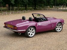
I have fell into the trap of believing the more air I get into the engine bay the better things will be, I am now starting to doubt this. It originally suited me to have maximum clearance at the front of my bonnet as it allowed me to get my radiator in without fouling the bonnet. The down side of this is that at high speed the bonnet can be seen to lift and starts to move around - this suggests to me that I have a high pressure area under bonnet which in turn leads to poor airflow through the engine bay. After reading several articles I have decided to try and understand what is going on aerodynamically. I plan to take numerous pressure measurements around the front of the vehicle / engine bay / under chassis in a bid to come up with some potential changes.
My aim is to have a high pressure in front of radiator, slightly lower in engine bay area and identify even lower pressure areas under the vehicle so that I can use these areas to draw the air from the engine bay, I will also try and determine if bonnet vents will actually improve the situation.
Over the weekend I have moved my radiator back and pulled the bonnet down at the front as far as adjustment would allow, after a quick run this morning this has stopped the bonnet lifting at speed with no adverse effects to the cooling performance, if anything it actually ran a little cooler than normal.
Next thing is to start taking pressure measurements, I have also made an undertray that I intend to try.
If you have any idea's, comments or theories please let me know.........

 Following numerous cardboard templates I have come up with something that seems to work quite well, I have fabricated an air box with filter that sits below the radiator.


 I don't expect a performance increase from any forced air effect but it should help overcome some of the restrictions of the filter and trunking. Having driven the car with the old and new intakes there is no noticeable difference in performance when travelling at speed.
 This hose is fitted with a 4mm restrictor, the idea being that as the pump draws coolant, from the radiator and header tank, it creates a lower pressure in the header tank, this in turn should draw any air in the thermostat housing back into the header tank.
 Made up a couple of pipes that fix to the rocker cover studs to keep it all looking tidy. Unfortunately not very easy to see in this picture.


