Saturday, May 31, 2008

Type 9 Gearbox Update

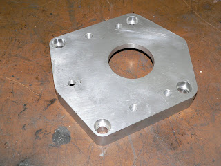
Finally got the CAD model sorted for the gearbox adapter and had the first one machined, fits ok although we have adjusted a couple of the dimensions after trying it on several boxes.


Had the first rear housing welded up, just need to make a support bush and re-drill the selector shaft, managed to move it forward by 107mm, looks like it should work ok.


Managed to pick up a couple more gearboxes of eBay, got a couple of 2.8 boxes which have a slightly taller first gear.

One thing to watch out for if you are considering fitting a Type 9 is there are a variety of input shaft dimensions, I have four boxes and three different lengths of input shaft. Learnt this today the hard way after fitting everything onto one of the boxes I had lying around, bolted it all to the back of an engine only to find out that my measurements were 20mm out, input shaft was only about 5mm into the flywheel. After alot of head scratching and thiking about other conversions / adapters I had seen, finally realised that the input shaft was 20mm shorter, must get myself a Type 9 gearbox manual.

Next job is to sort out a rear mounting, picked up a Sierra mount but I think it will be too wide to fit between the chassis rails. Been looking at what else is available and came across the one below which Westfield sell, bit pricey at £20 but may be the only option.

Been quoted around £100 for the propshaft from Dave Macs in Coventry, cant really order that untill the gearbox is fitted and I can give them the correct measurements.

I estimate that the gear lever position is going to be 35 mm back from its current position, still hoping it will all fit under the originall tunnel cover.

Plan is to have it all up and running for the RBRR (Round Britain Reliability Run) in October, hopefully sooner...................


Prescott

Had a great day out down at Prescott, managed to put a few more names and faces together.

Couple of clips of Dave Walker's 2500 Vitesse and my car in action


Saturday, March 29, 2008

Top Link Trial Fit

Managed to get another set of top links welded this week so I thought I'd trial fit them on my own car, the plans to get them on to Dave's Vitesse never materialised as he had to prep his Lemon for its MOT.

They certainly give the much needed wheel arch clearance required, the first photo shows how much the wheel sticks out past the wheel arch, had to run the front end fairly high to try and avoid my tyres being shredded.


The next photo is with the new top arms fitted.


With the spring and damper removed I was able to jack the wheel up well into the wheel arch.

This may look close but those are 215 tyres that are being stuffed in.....

I was expecting to have to modify the shock towers on the inner edges to clear the new arms. The attached photo shows the flanges bent back, I will probably end up removing about 5mm of material from the front edge to make sure there is enough clearance.

It didn't all go to plan, the top arms are very close to the spring when the suspension is unloaded, the brass adjuster and inner end of the top ball joint can touch the spring so careful positioning of the spring is required. Not good news as I was hoping these would be a direct replacement.

The following picture shows the car at its normal ride height with 1 degree of negative camber with no lower shims fitted - all clear.

The next photo shows the suspension unloaded, the brass adjuster will touch the spring. It is unlikely it will ever get to this condition while driving but I would have liked a bit more clearance.

I have a couple of options apart from living with it as it is, make the track rod end fit similar to Caterham, they have the top tube threaded and one lock nut on the outside, the down side of this is that you need to split the ball joint to alter the camber.

Or the second, would be to try it with 2 1/4" ID springs, after some very rough measurements were taken, I reckon they are about 3/8" smaller in diameter than the springs I currently have fitted, this should give me the extra clearance I need.

The good news is that Dave's Vitesse is already fitted with 2 1/4" ID springs so we can hopefully check them on his car next week.

Monday, March 24, 2008

Type 9 Gearbox

Managed to get myself a reconditioned Type 9 gearbox as a favour for doing some engine management work, its seemed a shame to start hacking around within it so I also got myself one off eBay, bargain £30.

My plan is to try and fit it without modifying the gearbox tunnel. I had been told that you can shorten the remote by 75mm, this still leaves me around 60mm short of the original gear lever position.

My first bell housing adapter is 30mm, once I am happy with the positioning, I will have another made from 25mm, In fact I ordered 10 billets so if your considering fitting a type 9 get in touch, I am currently having it drawn up in CAD so that I can have a batch CNC machined.

I have cut the tail housing as far as I can, with some major surgery I think I can shorten the remote by 105mm.


I have cut the rear casing almost back to the selector shaft seal.

The original remote housing has also be cut down as far as possible, the front section needs to be welded back on and then machined flat, I will also fit a small bush to support the selector shaft. This will then be welded to the tail housing.

The cast selector lever will need to be cut down by 10mm to fit into the smaller housing.

Hopefully this will give me a gear lever position 25 / 30mm backwards from current position, not sure if this will fit under the tunnel, that's a job for another day.

Top Arms

Still not yet got around to trial fitting, hopefully that will be sorted when I fit a set to Big Dave's Vitesse.


Fairly confident these will go on without a problem and hopefully create the required clearance, Dave's car is probably worse than mine for tyre to arch contact.

Managed to win an eBay auction for an adjustable tool post for my lathe, wasn't a straight forward fit but eventually got it sorted. I have modified one of the tool holders to hold the tubes so that I can cut the angles more accurately.


Now using a milling cutter which gives a much better finish, quick rub over with the file is all that is needed.

This set should be getting tigged up this week, need to order up some material to make the adjusters, going to have a go at using brass.

If these turn out ok, I will consider making a number of sets to sell on, I have been contacted by a number of people expressing an interest.

If you are considering ordering a set of these, please bear in mind that they are a critical suspension component, they will be made to the highest standard but I sugest they are inspected on a regular basis.

If you wish to fit these to your vehicle it will be at your own risk.

Post Options
Labels for this post:
e.g. scooters, vacation, fall


Update

Cant beleve its been 3 months since I last updated the blog, even worse not really done any work on the car, taken me a while to get going this year.

To get me into garage mentality, I agreed to help a friend restore a Mini, this has meant putting my car in another garage.


Having said that, it has got me back in the garage so I've been tinkering with other bits and pieces.

Tuesday, January 1, 2008

Happy New Year

New Year and time to get a to-do list together

In no particular order the following is a list of things I need to look at over the coming months, by hopefully putting them in print it will spur me on to complete some of them. Some of these are more achievable than others............

Fit the remaining interior trim, carpets arrived before Christmas, everything else is ready to be fitted.

Got a 4.11 diff that I'd like to try and compare to the 3.89 currently fitted.

Re-pack exhaust silencer, its starting to get a little noisy, also thinking about making up a centre pipe with a "cherry bomb" type silencer.

Make some new spindles for my throttle bodies and fit sealed roller bearings, also want to move the TPS switch to direct acting on the end of one of the throttle spindles - currently fitted on the end of the under slung linkage.

Complete and fit adjustable top arms.

Design and fabricate lower arms to take lower spherical ball joint.

Fit Caterham vertical links, AP calipers, vented disks etc.

Slight oil leak from the pushrod side of the head gasket, I'll monitor this over the next few weeks now that the engine breathing is sorted - otherwise I'll do this when I work on the throttle butterflies.

I've already cut up and re-welded my 3 into 1 collector as the exit pipe extended about 2" into the collector, might take a look at the primary to secondary collectors and see what's going on inside them. Also thinking about extending the 3 secondary pipes to the meet up at the back of the gearbox.

I'd like to get my car down to Emerald's rolling road for a mapping session sometime, probably after I've played around with the exhaust.

Like to get hold of some 195/40 R16 tyres to try in place of the 215/40's that are currently fitted, interested to see how it will effect the gearing and it will give me slightly more clearance - with the car fully loaded for the 10CR (No lowering block) I had very slight rubbing to the rear inner edge of the back wheel arch, also fouled on the front but hopefully the top arms will sort this.

Possibly change the gearbox to a 5 speed, probably Type 9, need to look at a few installations in other GT6's as I want to retain the original gearlever position. Also been looking at other options, Mercedes have a 6 Speed box that looks fairly compact, not seen one in the flesh yet so it might not be any good - would probably need to fabricate a new engine backplate if I went down this route - only ideas at the moment.

Look at doing something with the rear suspension, there are a couple of like minded people toying around with ideas at the moment so I might hang fire on this one, davesideways has some thoughts and more locally Andy Smith is building a V8 Vitesse and is keen to upgrade the diff and rear suspension. My ideas at the present are along the lines of some of the tried and tested stuff, Rotoflex uprights, MGF hubs and Metro driveshafts, I'd like to do away with the swing spring and go for coilovers mounted in the original shock positions. For starters I am thinking about bolting a box section to the top of the diff to give me top arm pick up points. Long term these could be fabricated on the chassis which would then give me the freedom to change to a stronger diff if required (Ford, Subaru, BMW all have LSD units available fairly cheap on ebay).

The gearbox and diff mods will all be dependant on how the current items perform, I would like to keep as much of the "original" drivetrain as possible, but there is enough evidence around to suggest that they wont last forever.

That's about it for the moment

If you are sitting there wondering why I am bothering to do the above modifications, I totally understand, I felt the same way when I started reading other peoples modifications, don't really have any defence, I like doing it and it becomes a challenge looking for the next improvement.

HAPPY NEW YEAR

Sunday, December 30, 2007

Engine Breather

Managed to get out in the car over the Christmas break, I was keen to see how my PCV valve worked - I was looking to see how much crankcase depression I was getting in various engine conditions - my measurement method was a digital manometer hooked up to my dipstick tube. Didn't get very far before I realised my first simple in-line valve was giving me too much depression, it wasn't able to control the pressure. The downside of this is that in extreme overrun I could potentially suck the oil into the intakes.

Time for Plan B, I had picked up a diaphragm type PCV valve, only problem was finding somewhere to fit it, no room on top of the intake manifolds.

After some pondering, decided to use my redundant distributor mounting, This needed a bit of machining to make it suitable, I also added a fixing point to hold the valve in place.

Not sure where I originally picked up this valve.

The valve pushes into the modified distributor housing and is held in with a small cap head bolt.

Fits quite neatly on the side of the block

Plumbed into the intakes via some 1/2" tubing pressed into the end of the manifolds.


Checked everything was fitted ok and started the engine, my pressure gauge was showing a 15 mbar depression at idle. Took it out for a drive, subjecting it to various operating conditions, the valve seemed to pretty much maintain a constant 15 mbar depression +/- 10 mbar. The original engine breather is now the fresh air into the engine crankcase and is fitted with a small restrictor to create the depression. With no restrictor it would be like having an air leak post throttle in the intake system.
Didn't get much else done, really need to trial fit my front upper wishbones - once I know they fit of I can get on and make another set with the thicker wall tubing and then ream the internal bores to the correct size.

Thursday, December 20, 2007

Trunnionless Link and Friends

Well, recently sold an injection kit so this has allowed me to spend a bit more on my car, collected the parts this week. Caterham style vertical links that will fit into spherical bearings in yet to be fabricated lower arms.


Alloy hubs with larger stub axle and improved bearings.

New 10" vented discs
And a very nice pair of AP Racing calipers, couldn't believe how light these calipers are, a friend has promised to get me a set of decent pads, they should arrive over Christmas.

No immediate plans to fit them yet, need to get the top and bottom arms fabricated first, also got another couple of engine related bits to finish off over Christmas so I've got to keep it mobile.

Top Arm Update

First pair of top arms have been welded, not bad, they have twisted very slightly and sprung in about 20 thou. The tube for the top ball joint has also distorted slightly making the adjusters a tight fit. I expected to have to make a couple of tweaks to perfect the design, this first set will be used to check for clearance issues with the front upright and to make sure I can get enough camber adjustment with no lower shims fitted.


To address some of the issues, the next arms will be made using the jig removed from its back plate so that a number of tack welds can be put in place on both sides to prevent distortion (springing). I'm also going to use slightly thicker tubing and then ream to the correct size.

Sunday, December 9, 2007

Front End Modifications

I've decide a while ago that I was going to convert the front uprights to Canley Classics / Caterham front uprights, primarily for the stronger stub axle as well as doing away with the lower trunnion. I had a stub shaft fail on the motorway a couple of years ago, initially thought it was a wheel bearing until I stripped it all down and found the shaft had broken at the start of the threads.


Anyway, that started me thinking about the front end, as I use quite a large wheel and tyre, I cant lower the front end too much as I end up with contact between the tyre and arch, while looking at various kit car set ups I have decided to fabricate my own adjustable top arms and do away with the shims on the lower arms. Hopefully this will pull the top of the wheel in a little more and give me some more tyre / arch clearance. If I need more I will fabricate lower arms that are slightly shorter and adjust the tops to compensate.


I have borrowed a home made tube notcher to get the right angle and profile

This made light work of cutting the tubes

As a couple of friends have shown interest I decide to knock up a jig to aid with the fabrication.

Just need to find a good local tig welder

Knocked up a couple of adjusters that will allow me to adjust the camber without having to remove the top ball joint.

I will hopefully get these welded together in the next week and then I can make sure they fit ok. I have used 25mm x 2mm wall thickness for the bush holders, 20mm x 2mm for the rest, all seamless tubing.

Got some drawings ready for the bottom arm, just need to see what effect the top one has before I make anymore jigs. The lower arm will be made to hold a spherical bearing.

Oil Leaks

Following the 10CR I developed several oil leaks, front seal, head gasket (push rod side) and rocker cover, all fairly standard but the strange thing was my engine had always been fairly leak free.

In a flash of inspiration sat on the front wheel staring at the engine drinking a cuppa, It suddenly dawned on me that I had modified my air intake system and that maybe it was having more of an effect than I had realised.

I connected a pressure gauge up to the dipstick tube and started the engine. Sure enough a small vacuum as expected as my breather system is plumed into my intake plenum upstream of the throttle bodies.

Took it out for a drive around town, still the same, slight depression on the engine. Found a nice quite road and increased the speed, at around 50 mph light throttle my gauge started to show a positive pressure in the crankcase, not good.

I pulled over and connected the pressure gauge directly to the intake plenum upstream of the throttle bodies in place of the engine breather and went for another drive, what I found was quite interesting, when travelling over 50 mph on light to half throttle I was registering a positive pressure in the intake system, good for performance bad for my breather system. Bearing in mind that on the 10CR (while on the autobahn), we could easily sit at 110+ mph on very light throttle, who knows how much pressure my crankcase was seeing, no wonder it developed oil leaks.

To sort the cause of the leaks I have decide to connect my breather system to the engine side of the throttle bodies and used a PCV valve to make sure it doesn't suck my oil out. I have cleaned up the engine bay and now await suitable weather to take it out for a run.


Mazda MX5 Seats

This post is in response to a recent topic on the Club Triumph Forum, It does not give all the details but highlights the main modifications.

One of the problems I had when fitting MX5 seats into my car was getting them to sit low enough and as far rearward as possible to give me enough room. At 6'1" I need as much legroom as possible.

One of the problem area's is the rear floor pan where it flares out at the rear of the tunnel. If you mount the seats on top of this you end up with very little headroom.


To get around this problem, I fully stripped the seats so that I was left with just the seat pan and then by trial fitting, removed enough material from the pan to clear the tunnel area, make sure you leave the seat hinge area untouched. Make sure you take into account the height of the runners (if you intend fitting them). I then welded in some 20mm angle iron to give the seat pan some strength in the hinge area. I have highlighted the modified area in the following picture.


I used some aftermarket seat runners as the seats I bought didn't have any, the inner runner needs to be modified to match the seat pan. On my setup I used the original MX5 seat mounting points on the outer runner and the front fixing on the inner runner, I welded in a nut for the rear fixing on the inner runner.

To mount the seat in the car, I made up 4 lugs that allowed me to use the original mounting points in the floor, you could probably gain another 15 mm headroom if you were to mount directly to the floor, you obviously then have no adjustment.

I used Securon seat belts with short steel stalks and bolted these directly to the seat in place of the MX5 seat belt stalk. There are slight differences between the driver and passenger seat but you basically make the same modifications.

The seats are very easy to strip apart, you remove the complete backrest as one assembly leaving it fully trimmed, then remove the cover and foam from the base, its all held in place with small wire clips that can be opened up, I'm sure you can buy these new along with the correct fitting tools but I just re-used the originals.

Tuesday, September 18, 2007

Car toons...........

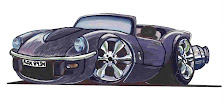
A friend of mine did a "quick sketch" of my car, I think it looks quite good.


Monday, September 17, 2007

Let There Be Light

Not really happy with the lighting following the 10 CR, never really noticed any issues in the past, then again never really had to drive it all night before. The biggest issue was the amount of glare / refection created when using main beam.

After looking at a TR6 recently at KD Triumph that had a HID kit fitted I was pretty impressed with the installation, I have HID's Xenon's on my everyday car so I'm well aware of the improvement they offer.

A quick search around the Internet and I came across a Bosch HID kit for a fairly reasonable price.


Fairly straight forward to fit, you get all the necessary brackets and fixings. There is a unit that needs to be fitted behind each lamp, I fixed these to some existing fittings on the wheel arch. There is also a control module that needs to be fitted on one side only, this needs an additional 12V feed. It also has a fly lead which plugs into the existing bulb connector. The bulbs basically fit the same as standard H4's, they just connect up to their own harness.


Difficult to show in a photograph but the light is much whiter and brighter as expected, they make the sidelights seem really yellow. I'll have to plan a night drive and see how they perform.

Sunday, September 16, 2007

Club Triumph 10 CR

What a trip................


I was a little apprehensive about doing this trip, mainly because my car had only covered about 2500 miles since its rebuild and I was about to double it. I needn't have worried, the car ran very well. I had spent the last couple of weeks checking, greasing etc etc and did not really expect to have any issues but you never really know in a car that is over 30 years old.

We averaged 27/28 mpg over the 2500 miles, 35 mpg was the best and 21 mpg the worst while tackling the mountain routes around Stelvio.

At one point we did suffer steering column shake and vibration but this was quickly diagnosed when the radio fell out and I realised that the H frame bolts had come undone.

We had another issue with a change in exhaust note and strange vibration which did get me a little worried, once we pulled into the service station this changed to a rattle from under the car, after a quick inspection, I found that the exhaust hanger U bolt had come loose, this was tightened and everything was fine again.

Apart from a little tyre to bodywork contact, that's about it.

I did learn quite alot about the car, this has given me a couple of things to investigate.

I had fitted 100 Watt bulbs for the event, while these were superb in complete darkness, with no reflective road markings or signs, If you tried to use main beam on anything reflective you were immediately blinded. My plan to overcome this is to fit some HID lights, they'll be the topic of another post.

My car handled exceptionally well, even in very wet conditions, what it didn't like was crossing road expansion joints in mid corner at high speeds, this became quite uncomfortable when going through series of tunnels during the trip. Not sure what I'm going to do about this as I cant slow down....... I think it looked more dramatic from the cars that were following as the car moved around. I don't plan on changing the wheel and tyre set up so I think I will have a mess around with the damping.

Developed a couple of oil leaks, one from the head gasket and one from the front crank seal, all pretty much standard stuff.

Might have a play around with diff ratios as the car does lack a little pull away performance, I think this is due to having 215/40 R16 tyres. I'm currently running with a 3.89 diff, I plan to swap this in the next few weeks to a 4.11 and see how that goes. I will happily trade some top speed for more acceleration.

I guess the only other thing to mention is that I had a pretty good co-driver, my brother Andy, he was quite happy to sit back and let me drive, when he did drive, he respected the fact that this was my car. We also met some great people during the event, only problem being that I didn't really remember any names but I'm sure we will meet up on future events.

The following link should take you to a short video of the GT6 at the Nurburgring http://uk.youtube.com/watch?v=_Ut2zz2841w

Thanks to Ellis and all at Club Triumph who organised the event.

Monday, August 27, 2007

Six Pack

I Wish..............

Couldn't find anybody locally that had a new distributor cap in stock on Saturday morning, so I decided to pull my plans forward and fit a wasted spark ignition system using a six pack coil. Originally I was going to do this after the 10CR but I got carried away.


Managed to pick up a couple of second hand coil packs and leads on eBay, I used a Mondeo V6 coil and cut the leads to suit.


Dead easy to wire in and set up, just a couple of extra wires to the ECU and then reconfigure the software to run a wasted spark system.


The most time consuming part was making a new bracket for the coil and blanking off the distributor hole.


I basically hacksawed my old distributor mounting casting, this was loctited in place leaving a small clearance to the oil pump drive shaft. I then made a plate, sealed it with RTV and bolted it in place.


Following a test drive, this seems to have cured my 6000 Rpm ignition issue, I now seem to have another issue up around 6800 - 6900 Rpm. Not sure if I need to fit stronger valve springs or I'm having issues with the crank trigger signal.


My trigger wheel is mounted on the back of my crank damper, not sure if the damper is resonating and causing an issue, I think this is unlikely as I'm able to log all the engine signals and all appear to seem OK - I need to investigate further............


My valve springs were bought from Chris Witor, I'll give him a call in the morning a see what he thinks.

Friday, August 24, 2007

Rolling Road

Spent the last month getting my car ready for the 10 CR, one of the main jobs has been to switch from my existing ECU to an Emerald K3. After making a new harness, trigger sensor bracket etc etc, finally got it up and running two weeks ago.

Spent the last couple of weeks mapping but couldn't get rid of an issue around 6000 Rpm, decided to get it booked in for a rolling road session. It was always the plan to optimise it on a rolling road, my only concern being that if the engine let go, I would be out of the 10 CR.

I'm glad to say all went well, the guys at Thor Racing managed to squeeze a bit more power and torque out of it. As with all figures these will vary from day to day, rolling road to rolling road however they do give an indication.


107 lb/ft @ 5580 Rpm

123 Bhp @ 6194 Rpm

Didn't manage to fix the 6000 Rpm issue but did a bit of investigation, basically its looking like a distributor cap issue, off to buy a new one in the morning.

A bit unfortunate as it was looking like there was a bit more power to come, I'm planning on setting the limiter at 7200 Rpm.